Fanuc control

Mazak control

Mazak Part Program, Offset Method, Control Key, cycle, Canned Cycle, Drilling Cycle, Macro - Cncprograming.blogspot.com.

Okuma control

Okuma Part Program, Offset Method, Control Key, cycle, Canned Cycle, Drilling Cycle, Macro - Cncprograming.blogspot.com.

Cincinnati control

Cincinnati Part Program, Offset Method, Control Key, cycle, Canned Cycle, Drilling Cycle, Macro - Cncprograming.blogspot.com.

Hass Turning Program

Fanuc Turning Part Program, Offset Method, Control Key, cycle, Canned Cycle, Drilling Cycle, Macro - Cncprograming.blogspot.com.

Showing posts with label G Codes. Show all posts

Cincinnati Machine G Codes List | Cincinnati Machine Programming Online Free Traning

Cincinnati Machine G Codes List:-

G00            =       Rapid Traverse (Linear)
G01            =       Linear Interpolation
G02            =       Circular Interpolation CW
G03            =       Circular Interpolation CCW
G04            =       Dwell
G09            =       Exact Stop
G12            =       Contouring Rotary Axis Unwind
G15.1         =       Polar Coordinate Programming (Blot Circle)
G15.2         =       Polar Coordinate Programming (Part Contour)
G150          =       Scaling Off
G151          =       Scaling On
G152          =       Position Towed Tailstock
G18            =       ZX Plane Select
G20            =       Straight or Taper Turning Cycle
G21            =       Straight or Taper Facing Cycle
G28            =       Auto Return to Reference Point
G29            =       Auto Return from Reference Point
G32            =       Threads per Inch Threading
G33            =       Threading Constant & Variable Lead
G34            =       Auto Multiple Pass Threading Cycle
G35            =       OD/ID Groove Cycle
G35.1         =       Face Groove Cycle
G36            =       Move To Next Operation Location
G36.1         =       Check End of Pattern
G40            =       Tool Nose Radius Compensation OFF
G41            =       Tool Nose Radius Compensation on LEFT
G42            =       Tool Nose Radius Compensation on RIGHT
G45            =       Acceleration/Deceleration ON
G46            =       Acceleration /Deceleration OFF
G52            =       Local Coordinate System
G60            =       Positioning Mode
G61            =       Contouring Mode
G62            =       Diameter Programming Mode
G63            =       Radius Programming Mode
G70            =       Inch Programming
G71            =       Metric Programming
G72            =       Stock Removal Finish Cycle
G73            =       Stock Removal Turning Cycle
G74            =       Stock Removal Facing Cycle
G75            =       Stock Removal Copy Cycle
G80            =       Reset Fixed Cycle
G81            =       Drill Cycle
G82            =       Counter Bore/ Spot Drill With Dwell Cycle.
G83            =       Deep Hole Drill (Peck Drill) Cycle
G84            =       Tap Cycle (Conventional)
G84.1         =       Rigid Tap Cycle
G85            =       Bore/Ream Cycle
G86            =       Bore Cycle
G87            =       Back Bore Cycle
G88            =       Web Drill / Bore Cycle
G89            =       Bore / Ream With Dwell Cycle
G90            =       Absolute Dimension Input
G91            =       Incremental Dimension Input
G92            =       Position Set
G92.1         =       Position Sets Setup Offset
G93            =       Inverse Time Federate
G94            =       Feed Per Minute Federate Mode
G95            =       Feed Per Revolution Federate Mode
G96            =       Constant Surface Speed
G97            =       Constant Spindle Speed Cancel(S=Rpm)
G98            =       Machine Coordinates (Tool Tip)
G98.1         =       Machine Coordinates
G99            =       Position Set Cancel

Hass machine G Code List


Haas G Code list:-

G00 RAPID POSITIONING MOTION (X,Z,U,W,B) (SETTING 10, 101)

G01 LINEAR INTERPOLATION MOTION (X,Z,U,W,B,F)

G01 CHAMFERING AND CORNER ROUNDING (X,Z,U,W,B,I,K,R,A,F)

G02 CW CIRCULAR INTERPOLATION MOTION (X,Z,U,W,I,K,R,F)

G03 CCW CIRCULAR INTERPOLATION MOTION (X,Z,U,W,I,K,R,F)

G04 DWELL (P) (P=seconds...milliseconds)

G05 FINE SPINDLE CONTROL MOTION (X,Z,U,W,R,F) (LIVE TOOLING)

G09 EXACT STOP, NON-MODAL

G10 PROGRAMMABLE OFFSET SETTING (X,Z,U,W,L,P,Q,R)

G14 MAIN-SPINDLE SHIFT TO SUB-SPINDLE

G15 MAIN-SPINDLE SHIFT TO SUB-SPINDLE CANCEL

G17 CIRCULAR MOTION XY PLANE SELECTION (G02,G03) (LIVE TOOLING)

G18 CIRCULAR MOTION ZX PLANE SELECTION (G02,G03) (SETTING 56)

G19 CIRCULAR MOTION YZ PLANE SELECTION (G02,G03) (LIVE TOOLING)

G20 VERIFY INCH COORDINATE POSITIONING (SETTING 9 needs to be INCH)

G21 VERIFY METRIC COORDINATE POSITIONING (SETTING 9 needs to be METRIC)

G28 MACHINE ZERO RETURN THRU REF. POINT (X,Z,U,W,B) (Fanuc)

G29 MOVE TO LOCATION THROUGH G29 REF. POINT (X,Z) (Fanuc)

G31 FEED UNTIL SKIP FUNCTION (X,Z,U,W,F)

G32 THREAD CUTTING PATH, MODAL (X,Z,U,W,F)

G40 TOOL NOSE COMPENSATION CANCEL G41/G42 (X,Z,U,W,I,K) (SETTING 56)

G41 TOOL NOSE COMPENSATION, LEFT (X,Z,U,W) (SETTING 43, 44, 58)

G42 TOOL NOSE COMPENSATION, RIGHT (X,Z,U,W) (SETTING 43, 44, 58)

G50 SPINDLE SPEED MAXIMUM RPM LIMIT (S)

G51 RETURN TO MACHINE ZERO, CANCEL OFFSET (Yasnac)

G52 WORK OFFSET COORDINATE POSITIONING (Yasnac)

G52 GLOBAL WORK COORDINATE SYSTEM SHIFT (Fanuc)

G53 MACHINE COORDINATE POSITIONING, NON-MODAL (X,Z,B)

G54 WORK OFFSET COORDINATE POSITIONING #1 (SETTING 56)

G55 WORK OFFSET COORDINATE POSITIONING #2

G56 WORK OFFSET COORDINATE POSITIONING #3

G57 WORK OFFSET COORDINATE POSITIONING #4

G58 WORK OFFSET COORDINATE POSITIONING #5

G59 WORK OFFSET COORDINATE POSITIONING #6

G61 EXACT STOP, MODAL (X,Z)

G64 EXACT STOP G61 CANCEL (SETTING 56)

G65 MACRO SUB-ROUTINE CALL

G70 FINISHING CYCLE (P,Q)

G71 O.D. / I.D. STOCK REMOVAL CYCLE (P,Q,U,W,I,K,D,S,T,R1,F) (SETTING 72, 73)

G72 END FACE STOCK REMOVAL CYCLE (P,Q,U,W,I,K,D,S,T,R1,F) (SETTING 72, 73)

G73 IRREGULAR PATH STOCK REMOVAL CYCLE (P,Q,U,W,I,K,D,S,T,F)

G74 FACE GROOVING, or HIGH SPEED PECK DRILL CYCLE (X,Z,U,W,I,K,D,F) (SETTING 22)

G75 O.D. / I.D. PECK GROOVING CYCLE, (X,Z,U,W,I,K,D,F) (SETTING 22)

G76 THREAD CUTTING CYCLE, MULTIPLE PASS (X,Z,U,W,I,K,A,D,F) (SETTING 86, 95, 96, 99)

G77 FLATTING CYCLE (I,J,L,R,S,K) (LIVE TOOLING)

G80 CANCEL CANNED CYCLE (SETTING 56)

G81 DRILL CANNED CYCLE (X,Z,W,R,F)

G82 SPOT DRILL / COUNTERBORE CANNED CYCLE (X,Z,W,P,R,F)

G83 PECK DRILLING CANNED CYCLE (X,Z,W,I,J,K,Q,P,R,F) (SETTING 22, 52)

G84 TAPPING CANNED CYCLE (X,Z,W,R,F)

G85 BORE IN, BORE OUT CANNED CYCLE (X,Z,U,W,R,L,F)

G86 BORE IN, STOP, RAPID OUT CANNED CYCLE (X,Z,U,W,R,L,F)

G87 BORE IN, STOP, MANUAL RETRACT CANNED CYCLE (X,Z,U,W,R,L,F)

G88 BORE IN, DWELL, MANUAL RETRACT CANNED CYCLE (X,Z,U,W,P,R,L,F)

G89 BORE IN, DWELL, BORE OUT CANNED CYCLE (X,Z,U,W,P,R,L,F)

G90 O.D. / I.D. TURNING CYCLE, MODAL (X,Z,U,W,I,F)

G92 THREADING CYCLE, MODAL (X,Z,U,W,I,F) (SETTING 95, 96)

G94 END FACING CYCLE, MODAL (X,Z,U,W,K,F)

G95 END FACE LIVE TOOLING RIGID TAP (X,Z,W,R,F)

G96 CONSTANT SURFACE SPEED, CSS ON (S)

G97 CONSTANT NON-VARYING SPINDLE SPEED, CSS OFF (S) (SETTING 56)

G98 FEED PER MINUTE (F)

G99 FEED PER REVOLUTION (F) (SETTING 56)

G100 MIRROR IMAGE CANCEL G101

G101 MIRROR IMAGE (X,Z) (SETTING 45, 47)

G102 PROGRAMMABLE OUTPUT TO RS-232 (X,Z)

G103 LIMIT BLOCK LOOKAHEAD (P0 - P15 max. for number control looks ahead)

G105 SERVO BAR COMMAND

G110-G111 WORK OFFSET COORDINATE POSITIONING #7- #8

G112 CARTESIAN TO POLAR TRANSFORMATION

G113 CARTESIAN TO POLAR TRANSFORMATION CANCEL

G114-G129 WORK OFFSET COORDINATE POSITIONING #9 - #24

G159 BACKGROUND PICKUP / PART RETURN

G160 APL AXIS COMMAND MODE ON

G161 APL AXIS COMMAND MODE OFF

G184 REVERSE TAPPING CANNED CYCLE (X,Z,W,R,F) (SETTING 130)

G187 ACCURACY CONTROL FOR HIGH SPEED MACHINING (E) (SETTING 85)

G194 SUB-SPINDLE / TAPPING CANNED CYCLE

G195 LIVE TOOLING VECTOR TAPPING (X,F)

G196 LIVE TOOLING VECTOR TAPPING REVERSE (X,F)

G200 INDEX ON THE FLY (X,Z,U,W,T)

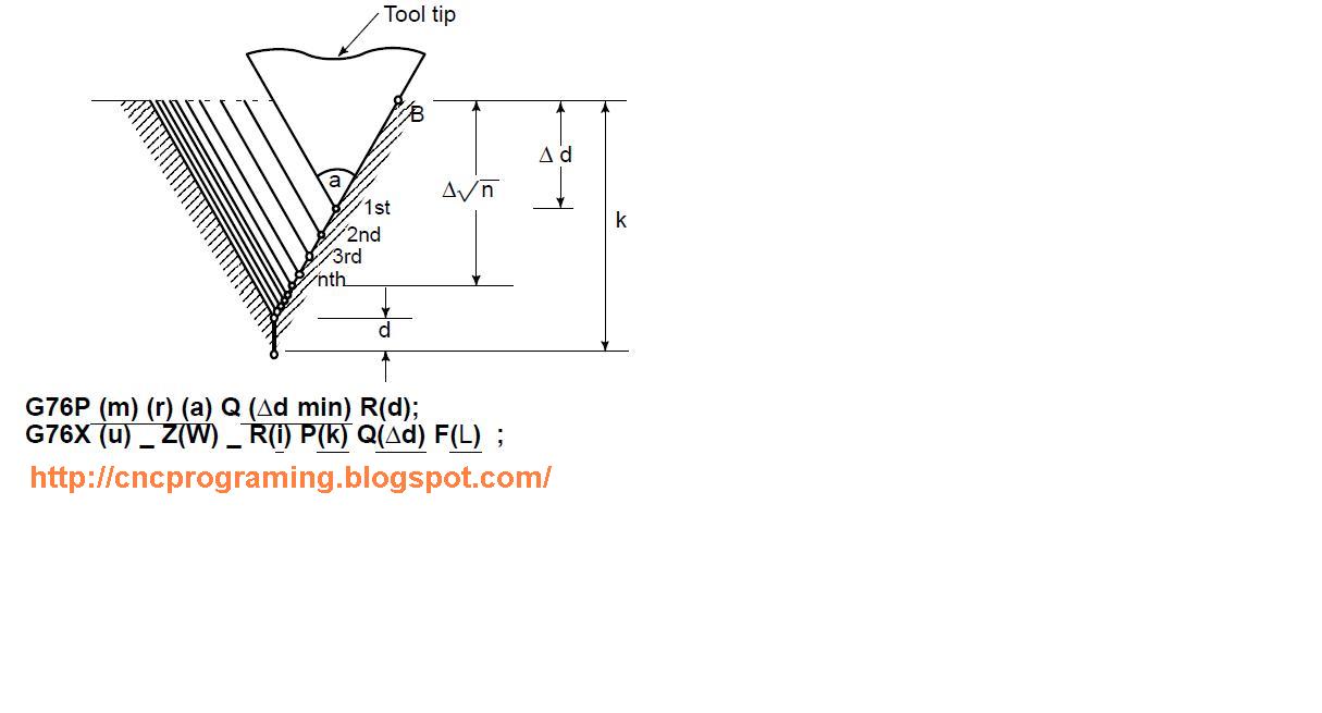
Multiple Thread Cutting Cycle G76

Multiple Thread Cutting Cycle G76:-
G76P (m) (r) (a) Q (Δd min) R (d);
G76X (u) _ Z(W) _ R(i) P(k) Q(?d) F(L) ;

m                =        Repetitive Count In Finishing (1 To 99)
r                  =        Chamfering Amount
a                  =        Angle of Tool Tip
P                  =        m, r, and a are specified by address P at the same time.
Δdmin          =        Minimum Cutting Depth (Specified By the Radius Value)
d                 =        Finishing Allowance
I                  =        Difference Of Thread Radius If I = 0, Ordinary Straight       Thread Cutting Can Be Made.
K                 =        Height of Thread
Δd                =        Depth of Cut in 1st Cut (Radius Value)
L                 =        Lead Of Thread (Same as G32).

Example:-
Notes:-
1.   In the blocks where the multiple repetitive cycle are commanded, the addresses P, Q, X, Z, U, W, and R should be specified correctly for each block.
2.    In the blocks in which G70, G71, G72, or G73 are commanded and between the sequence number specified by P and Q, M98 (subprogram call) and M99 (subprogram end) cannot be commanded.
3.   In the blocks between the sequence number specified by P and Q, the following commands cannot be specified.
One shot G code except for G04 (dwell)
01 group G code except for G00, G01, G02, and G03
06 group G code
M98 / M99
4.    When G70, G71, G72, or G73 is executed, the sequence number specified by address P and Q should not be specified twice or more in the same program.
5.    The blocks between the sequence number specified by P and Q on the multiple repetitive cycle must not be programmed by using “Direct Drawing Dimensions Programming”.
6.   The multiple repetitive cycle cannot be executing during DNC operation.
7.   Interruption type custom macro cannot be executed during executing the multiple repetitive cycle.
Alarm:-
1.   In the block which is specified by address P of G71, G72 or G73, G00 or G01 group should be commended. If it is not commanded, P/S alarm No.65 is generated.
2.   In MDI mode, G70, G71, G72, or G73 cannot be commanded. If it is commanded, P/S alarm No. 67 is generated. G74, G75, and G76 can be commanded in MDI mode.


Fanuc Machine G codes List

G codes:-    
  • Ø  G00                  Positioning (Rapid traverse)
  • Ø  G01                  Linear interpolation (Cutting feed)
  • Ø  G02                  Circular interpolation CW
  • Ø  G03                  Circular interpolation CCW
  • Ø  G04                  Dwell
  • Ø  G07.1               Cylindrical interpolation
  • Ø  G10                  Programmable data input
  • Ø  G11                  Programmable data input cancel
  • Ø  G12.1               Polar coordinate interpolation mode
  • Ø  G13.1               Polar coordinate interpolation cancel mode
  • Ø  G17                  XpYp plane selection
  • Ø  G18                  ZpXp plane selection
  • Ø  G19                  YpZp plane selection
  • Ø  G20                  Input in inch
  • Ø  G21                  Input in mm
  • Ø  G22                  Stored stroke check function on
  • Ø  G23                  Stored stroke check function off
  • Ø  G25                  Spindle speed fluctuation detection off
  • Ø  G26                  Spindle speed fluctuation detection on
  • Ø  G27                  Reference position return check
  • Ø  G28                  Return to reference position
  • Ø  G30                  2nd, 3rd and 4th reference position return
  • Ø  G31                  Skip function
  • Ø  G32                  Thread cutting
  • Ø  G34                  Variable–lead thread cutting
  • Ø  G36                  Automatic tool compensation X
  • Ø  G37                  Automatic tool compensation Z
  • Ø  G40                  Tool nose radius compensation cancel
  • Ø  G41                  Tool nose radius compensation left
  • Ø  G42                  Tool nose radius compensation right
  • Ø  G50                  Coordinate system setting or max. spindle speed setting
  • Ø  G50.3               Work piece coordinate system preset
  • Ø  G50.2               Polygonal turning cancel
  • Ø  G51.2               Polygonal turning
  • Ø  G52                  Local coordinate system setting
  • Ø  G53                  Machine coordinate system setting
  • Ø  G54                  Work piece coordinate system 1 selection
  • Ø  G55                  Work piece coordinate system 2 selection
  • Ø  G56                  Work piece coordinate system 3 selection
  • Ø  G57                  Work piece coordinate system 4 selection
  • Ø  G58                  Work piece coordinate system 5 selection
  • Ø  G59                  Work piece coordinate system 6 selection
  • Ø  G65                  Macro calling
  • Ø  G66                  Macro modal call
  • Ø  G67                  Macro modal call cancel
  • Ø  G70                  Finishing cycle
  • Ø  G71                  Stock removal in turning
  • Ø  G72                  Stock removal in facing
  • Ø  G73                  Pattern repeating
  • Ø  G74                  End face peck drilling
  • Ø  G75                  Outer diameter/internal diameter drilling
  • Ø  G76                  Multiple threading cycle
  • Ø  G80                  Canned cycle for drilling cancel
  • Ø  G83                  Cycle for face drilling
  • Ø  G84                  Cycle for face tapping
  • Ø  G86                  Cycle for face boring
  • Ø  G87                  Cycle for side drilling
  • Ø  G88                  Cycle for side tapping
  • Ø  G89                  Cycle for side boring
  • Ø  G90                  Outer diameter/internal diameter cutting cycle
  • Ø  G92                  Thread cutting cycle
  • Ø  G94                  Endface turning cycle
  • Ø  G96                  Constant surface speed control
  • Ø  G97                  Constant surface speed control cancel
  • Ø  G98                  Per minute feed
  • Ø  G99                  Per revolution feed
  • Ø  G90                  Absolute programming
  • Ø  G91                  Incremental programming
  • Ø  G98                  Return to initial level
  • Ø  G99                  Return to R point level

Followers

Face book

Twitter Delicious Facebook Digg Stumbleupon Favorites More