Mazak control
Mazak Part Program, Offset Method, Control Key, cycle, Canned Cycle, Drilling Cycle, Macro - Cncprograming.blogspot.com.
Okuma control
Okuma Part Program, Offset Method, Control Key, cycle, Canned Cycle, Drilling Cycle, Macro - Cncprograming.blogspot.com.
Cincinnati control
Cincinnati Part Program, Offset Method, Control Key, cycle, Canned Cycle, Drilling Cycle, Macro - Cncprograming.blogspot.com.
Hass Turning Program
Fanuc Turning Part Program, Offset Method, Control Key, cycle, Canned Cycle, Drilling Cycle, Macro - Cncprograming.blogspot.com.
Showing posts with label Turning. Show all posts
Multiple Thread Cutting Cycle G76
3:46 AM
Sivakumar
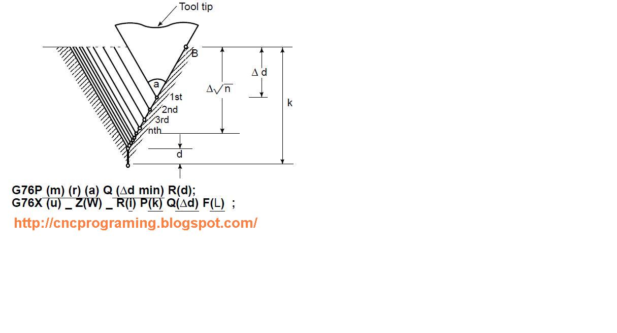
G76P (m) (r) (a) Q (Δd min) R (d);
G76X (u) _ Z(W) _ R(i) P(k) Q(?d) F(L) ;
m = Repetitive Count In Finishing (1 To 99)
r = Chamfering Amount
a = Angle of Tool Tip
P = m, r, and a are specified by address P at the same time.
Δdmin = Minimum Cutting Depth (Specified By the Radius Value)
d = Finishing Allowance
I = Difference Of Thread Radius If I = 0, Ordinary Straight Thread Cutting Can Be Made.
K = Height of Thread
Δd = Depth of Cut in 1st Cut (Radius Value)
L = Lead Of Thread (Same as G32).
Notes:-
1. In the blocks where the multiple repetitive cycle are commanded, the addresses P, Q, X, Z, U, W, and R should be specified correctly for each block.
2. In the blocks in which G70, G71, G72, or G73 are commanded and between the sequence number specified by P and Q, M98 (subprogram call) and M99 (subprogram end) cannot be commanded.
3. In the blocks between the sequence number specified by P and Q, the following commands cannot be specified.
One shot G code except for G04 (dwell)
01 group G code except for G00, G01, G02, and G03
06 group G code
M98 / M99
4. When G70, G71, G72, or G73 is executed, the sequence number specified by address P and Q should not be specified twice or more in the same program.
5. The blocks between the sequence number specified by P and Q on the multiple repetitive cycle must not be programmed by using “Direct Drawing Dimensions Programming”.
6. The multiple repetitive cycle cannot be executing during DNC operation.
7. Interruption type custom macro cannot be executed during executing the multiple repetitive cycle.
Alarm:-
1. In the block which is specified by address P of G71, G72 or G73, G00 or G01 group should be commended. If it is not commanded, P/S alarm No.65 is generated.
2. In MDI mode, G70, G71, G72, or G73 cannot be commanded. If it is commanded, P/S alarm No. 67 is generated. G74, G75, and G76 can be commanded in MDI mode.
Transverse Cut-Off Cycle G75 Or Diameter Grooving Cycle:-
5:14 AM
Sivakumar
Transverse Cut-Off Cycle G75 Or Diameter Grooving Cycle:-
Overview:-
This function is used for smooth disposal of machining chips in transverse cut-off machining. This allows easy disposal of machining chips in face turning as well. Both G74 and G75 which are used for cutting off, grooving or drilling, are a cycle to give the escape of a tool automatically. Four patterns which are symmetrical with each other are available. During single block operation, all the blocks are executed step by step.
Programming Format:-
G75 R (1st ) ;
G75 x__ Z__ P__ Q__ R__ F__ S__ T__ ;
Description:-
R = Distance of Return
X = Absolute Value / Incremental Value of X-Axis
Z = Absolute Value / Incremental Value of Z Axis
P = X-axis cut depth
Q = Z-Axis Movement Distance
R = ( 2nd R )Tool Escape Distance at the Bottom of Cut
F = Feed Rate
S = S Command
T = T Command
Sample Program:-
G00 G96 G98 ;
G28 U0 W0 ;
X102. Z-20. ;
G75 R2. ;
G75 W-15. X70. P6. Q5. F150 S100 M3 ;
G28 U0 W0 ;
M30 ;
Face Grooving Cycle G74 Or Longitudinal Cut-Off Cycle
3:39 AM
Sivakumar
Face Grooving Cycle G74 Or Longitudinal Cut-Off Cycle
This function is used for smooth disposal of machining ships in longitudinal cut-off machining. For SS materials which produce hard-to-cut machining chips this function can be managed for easy machining chip disposal. You can use this cycle for drilling
Programming Format:-
G74 R__;
G74 X__ Z__ P__ Q__ R__ F__ S__ T__;
Description:-
R = Distance of Return
X = Absolute Value / Incremental Value of X-Axis
Z = Absolute Value / Incremental Value of Z Axis
P = X-Axis Movement Distance
Q = Z-axis cut depth
R = ( 2nd R )Tool Escape Distance at the Bottom of Cut
F = Feed Rate
S = S Command
T = T Command
Drilling Cycle :-
For drilling X, P and R (2nd ) are not required .Omit these dada.
Notes:-
1. During single block operation, all the blocks are executed step by step2. Omission of address X , P and R( 2nd ) provides the operation of Z axis alone , resulting in peck drilling cycle.3. R ( 1st ) and R ( 2nd ) are both command values address R. the differentiation is given by whether Z is commanded together . that is ,the command R together with Z results in the flat of R ( 2nd )4. Cycle operation is performed in the block where Z is commanded
Sample program:-
G00 G96 G98 ;
G28 U0 W0 ;
X100. Z2.0 ;
G72 R2. ;
G72 U-50. Z-40. P5. Q7. F150. S100 M3 ;
G28 U0 W0 ;
M30 ;
Finishing Cycle G70 Fanuc Control CNC Programming
2:48 AM
Sivakumar
Finishing Cycle G70 Fanuc Control CNC Programming
After roughing have been carried out by the G71 to G73 commands, finishing can be performed by following programming format.
G70 P__ Q__
P = finish shape start sequence number
Q = finish shape end sequence number
Example:-
O1234 ;
;
;
N100 G70 P200 Q300 ;
;
;
M30;
How to make Thread Program In G32 Fanuc Machine
3:46 AM
Sivakumar
Thread Programming : - (G32)
Function and purpose:-
The G32 command control the federate of the tool in synchronization with the spindle rotation and so this enables both the straight and scrolled thread cutting of constant leads and the continuous thread cutting.
Detailed Description:-
1. Constant surface speed control function should not be used here.
2. The spindle speed should be kept constant throughout from the Roughing until Finishing.
3. When a threading command is programmed during tool nose R compensation ,the compensation is temporarily cancelled and the threading executed.
4. The threading command waits for the single rotation synchronization signal of the rotary encoder and start movement.
Notes:-
The number of thread in the long axis direction is assigned as the number of thread per inch
Programming Format:-
Straight thread:-
G00 X__ ( Thread cutting Diameter )
G32 Z__ F__ ( Thread Length & F= pitch )
G00 X__ ( X axis Position return )
Taper thread:-
G00 X__
G32 X__ Z__ F__
G00 X__
Example:-
M20 x 1.5 P x 4MM Length
( OD THREAD )
N1 G28 U0.0 W0.0 ; ( Home Position )
N2 G00 T0101 ; ( Number One Tool Selection )
N3 G97 S500 M03; ( Spindle Speed And Direction Selection )
N4 G00 X22.0 Z1.0 M08; ( safe position & coolant on )
N5 G00 X18.50 ; ( Thread cutting point X Axis )
N6 G32 Z-4.00 F1.5; ( Thread cutting 4MM length )
N7 G00 X22.0; ( Position Return )
N8 M09 M05 ; ( coolant off , spindle stop )
N9 G28 U0.0 W0.0; ( Home Position Return )
M30; ( Program End )
%
About Thread or what is mean by thread?
10:28 AM
Sivakumar
Threading:-
Out of different fastening process threading is one. This process is widely used because it doesn’t join two parts permanently giving the flexibility of disassembling them when needed
What is a Thread?
A thread is a raised, helical rib or ridge around the exterior of a cylindrically shaped object or the interior of a hole. Common threaded parts include screws, nuts, and bolts. Threads have two basic applications: fastening and the transfer or control of motionApplication:-
Thread is one of the most used processes in mechanical field. In everyday life we come across through many type of components that have a thread in it. Take example of a pen cap or a water bottle etc.
Understanding a thread:
v The crest is the peak or top of the thread ridge that lies between two flanks. Its size and shape may vary depending on the thread type.
v The flank is an angled side of a thread. Threads have two flanks.
v The root is the bottom of the thread that lies between the flanks. Its size and shape also may vary depending on the thread type.
Type of thread:-
Depending on Geometry thread is classified into two categories. A) Straight threads B) taper thread.
Straight threads can be classified into single start or multi start threads.

Important parameters on the thread:-
- v The pitch point is the position on the thread where the distance between the flanks is equal in both the ridge and the groove.
- v The pitch diameter is the measured distance between the pitch points in the groove between the threads. It is one of the most important dimensions in thread inspection.
- v The depth is the length of the vertical space from the root to the crest of a thread.
- v The major diameter is the distance between the crests of a thread. It is the widest diameter on a thread.
- v The minor diameter is the distance between the roots of a thread. It is the smallest diameter on a thread.
- v Thread form which is the shape of the thread example 90 degree, 60 degree threads etc.
Start, Pitch, and Lead
Start:-
Start refers to the number of different individual threads that wrap around the cylinder. The number of threads equals the number of starts. It means how many start points are there in a thread.
Pitch:-
The distance from one thread crest to the next. For threads manufactured in inches, pitch is expressed in inches as a fraction. It is not the number of threads per inch, but the number "one" divided by the number of threads per inch. For metric threads, pitch is expressed in millimeters.Lead:-
Lead is the distance that a screw travels in one revolution. This distance is equal to the pitch of the screw multiplied by the number of starts on the screw. On a single-thread screw, the lead equals the pitch.
Threads can be manufactured in one of the below mentioned process.
- v Thread cutting and thread milling are cutting methods that use a single-point tool and multi-point tool, respectively, to create threads on a blank or work piece.
- v Thread rolling is a cold forming process that uses a die to deform metal and press it into the shape of threads. Figure 2 shows the mechanism that holds the dies.
- v Thread tapping uses a drill-like tool to either cut or form threads on the ID of a previously drilled hole.
- v Thread grinding uses an abrasive wheel to wear away material and create the thread. Thread grinding is the most precise method of producing threads
Threads may be cut using multiple methods. OD threads may be cut on a lathe or a mill. Both methods begin with a larger blank or work piece and use a cutting tool to remove material and shape the threads. In general, cutting threads is an efficient method, but it has its drawbacks. Cutting produces chips that can interfere with the threads, and the process can cause stress cracks in the metal.A lathe uses a single-point tool, to cut the threads into the blank or work piece, which is held either between centers or in a chuck. The cutting tool is fed into the blank and moved sideways along the rotating piece. On the first pass, the tool is often used to scratch the surface so that the operator can inspect the scratch and verify the tool settings. Then the tool makes multiple passes, cutting deeper each time the tool travels the length of the cylinder.
Milling is another form of cutting. Thread milling is performed similarly to lathe cutting except that a multi-point tool is used. Also, when using a mill, it is usually the tool, not the work piece, that rotates. Milling can be performed more quickly than other methods, but it is generally not recommended for manufacturing smaller threads.
To continue ……………
How to make Cylindrical interpolation G07.1 program
6:51 AM
Sivakumar
Cylindrical interpolation G07.1
Cylindrical interpolation function refers to a function by which the sides of a cylindrical workpiece are machined .the cylindrical interpolation function capable of programming in the form in which the sides of a cylinder are spread can very prepare programs including cylindrical cam grooving.
G07.1 C___ ; Cylindrical Interpolation mode ( C:Cylindrical Radius )
G07.1 C___ ; Cylindrical interpolation cancel mode
Detail:-
The moving distance of rotational axis commanded with an angle is converted to the linear distance on the circumference in CNC. After the conversion, linear interpolation or circular interpolation is given with the other axis .After the interpolation, the calculated movement is converted again to the moving distance of rotational axis.
Notes:-
1. Plane selection:-
Giving the circular interpolation between the rotational axis and other linear axis during cylindrical mode requires the command of plane selection (G17, G18, and G19).
Example:-
G18 Z__ C__ ;
G02 / G03 Z__ C__ R__;
2. Radius designation
The circular radius by word address I, J, or K cannot be commended during cylindrical interpolation mode. The circular radius is commanded by address R. the radius must be commanded not with angle, but with MM or Inch.
3. Tool nose radius compensation :-
Giving the tool nose radius compensation during cylindrical interpolation mode requires the command of plane selection as with the circular interpolation. However, giving the tool nose radius compensation requires start-up and cancel during cylindrical interpolation mode. Establishing a cylindrical interpolation mode with the tool nose radius compensation given does not provide proper compensation.
4. Positioning:-
Positioning cannot be accomplished during cylindrical interpolation mode. Positioning requires establishing a cylindrical interpolation cancel mode.
Notes:-
When the cylindrical radius is not commanded, a cylinder is defined taking as radius current value of X-axis when G07.1 is commanded.